Why Lab Validation Does Not Reflect Production Reality
Lab validation confirms that a configuration can work under ideal conditions. It does not guarantee that it will behave the same way in production. Understanding that limitation is critical.
The lab uses clean fiber, known connectors, and stable configs. Production uses whatever got installed three years ago by a contractor who left no documentation.
A link that tested clean in the lab showed 1.5 dB more loss in production. Nobody had counted the connectors.
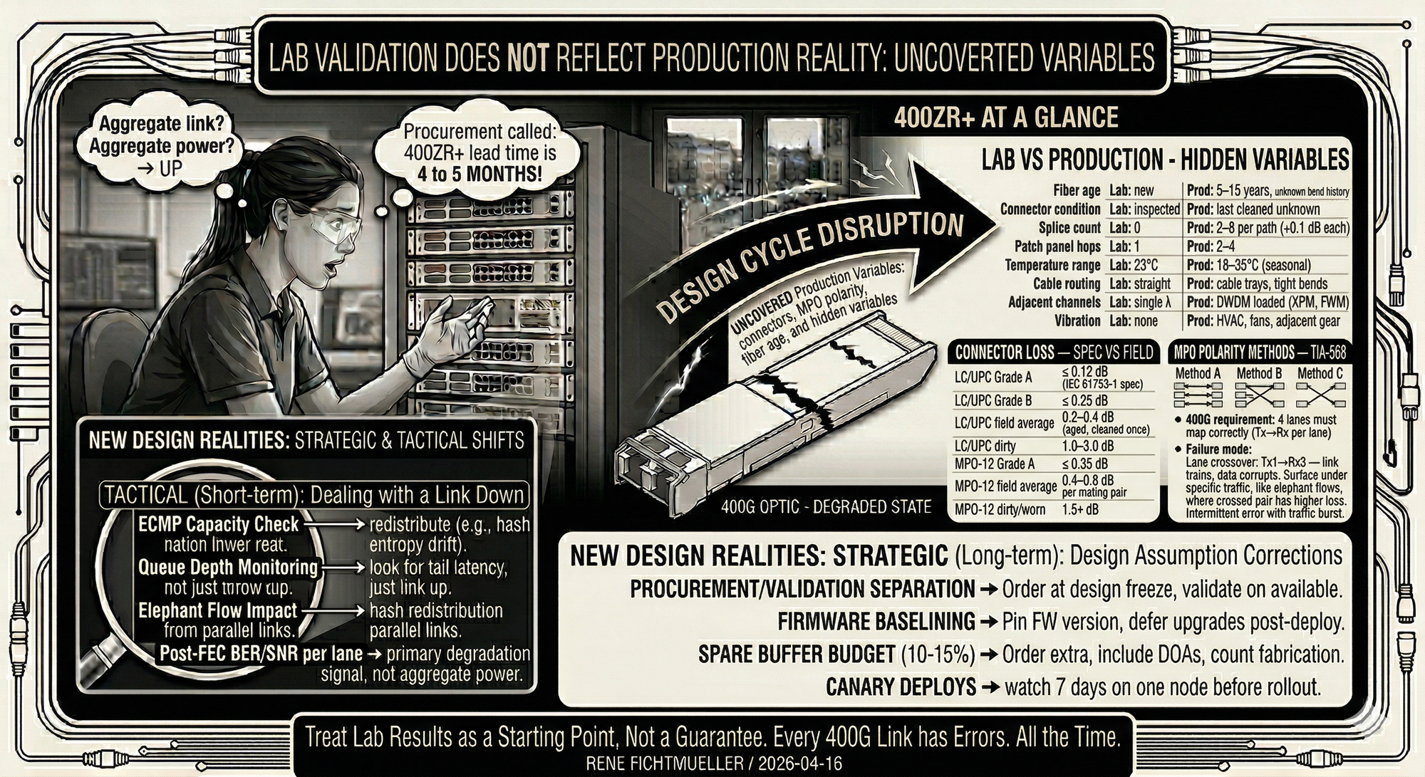
LC/UPC Grade B ≤ 0.25 dB
LC/UPC field average 0.2–0.4 dB (aged, cleaned once)
LC/UPC dirty 1.0–3.0 dB
MPO-12 Grade A ≤ 0.35 dB
MPO-12 field average 0.4–0.8 dB per mating pair
MPO-12 dirty/worn 1.5+ dB
Six connectors in the path. Three mating pairs. Each adding 0.3–0.5 dB more than the design spreadsheet assumed. Together they ate 1.5 dB of margin that only existed on paper.
At 10G, 1.5 dB of surprise loss is a rounding error. You have 15+ dB of headroom. At 400G PAM4 with tight budgets, 1.5 dB is the difference between stable operation and FEC stress.
A different deployment. Intermittent errors on a 400G link. The MPO configuration had been changed during a previous upgrade. Nobody updated the documentation.
Method B (flipped) Key up → Key down, Position 1→12
Method C (pairs) Key up → Key up, adjacent pairs swapped
400G requirement 4 lanes must map correctly (Tx→Rx per lane)
Failure mode Lane crossover: Tx1→Rx3 — link trains, data corrupts
400G uses four lanes. Each transmitter must reach the correct receiver. A polarity error doesn't always kill the link. The SerDes on both sides can train on the wrong lane pairing. The result is intermittent corruption that traces to nothing obvious.
This one only surfaced under specific traffic patterns. Certain lanes carried more load. The crossed pair had slightly different loss characteristics. Under light load, FEC covered it. Under heavy load, it didn't.
Connector condition Lab: inspected | Prod: last cleaned unknown
Splice count Lab: 0 | Prod: 2–8 per path (+0.1 dB each)
Patch panel hops Lab: 1 | Prod: 2–4
Temperature range Lab: 23°C | Prod: 18–35°C (seasonal)
Cable routing Lab: straight | Prod: cable trays, tight bends
Adjacent channels Lab: single λ | Prod: DWDM loaded (XPM, FWM)
Vibration Lab: none | Prod: HVAC, fans, adjacent gear
The lab tells you a configuration can work under controlled conditions. It doesn't tell you it will work in a building where the fiber was pulled in 2014, run through three patch panels, and terminates in an MPO that hasn't been inspected since installation.
2. Inspect every connector 400× microscope, IEC 61300-3-35 pass/fail
3. Document polarity Verify each lane with VFL or polarity tester
4. Temperature soak Run link 72h, capture FEC stats at temp extremes
5. Load test RFC 2544 + Y.1564 with background traffic
6. Baseline FEC metrics Record pre-FEC BER per lane at deployment
7. Power budget margin Require ≥3 dB margin after all measured losses
Even with all of this, lab testing remains an approximation. Fiber degrades. Connectors wear. Configurations drift. A link that passes today can degrade six months from now without anyone touching it.
Lab results give you a starting point. Treat them as one. Teams that get surprised by production issues are teams that treated lab results as a guarantee.