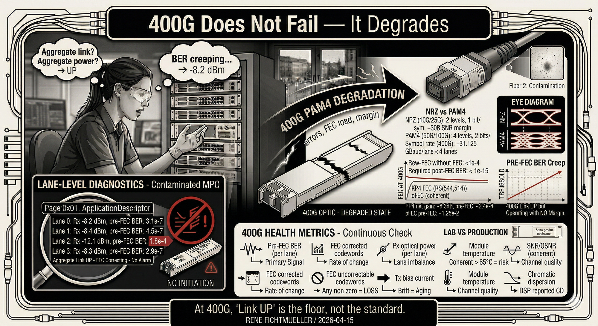
400G Does Not Fail — It Degrades
An interface can be up while the link is already operating outside a stable margin. At 400G, a link being 'up' is not a useful indicator of health.
At 10G, a link works or it doesn't. At 400G, a link can be up and broken at the same time.
10G and 25G run NRZ: two signal levels, one bit per symbol. The eye diagram is wide open. Margins are generous. Binary behavior.
400G runs PAM4 across four lanes of 100G each. Four signal levels, two bits per symbol. The eye diagram has three openings instead of one. Each is roughly a third the height of an NRZ eye.
PAM4 (50G/100G) 4 levels, 2 bits/symbol, ~9.5 dB less margin
Symbol rate (400G) ~53.125 GBaud per lane × 4 lanes
Raw BER without FEC PAM4: ~1e-4 (unusable)
Required post-FEC BER < 1e-15 (error-free)
PAM4 cannot function without Forward Error Correction. The raw bit error rate is orders of magnitude worse than NRZ. FEC closes the gap between "noise" and "usable link."
Every 400G link has errors. All the time. The question is whether FEC corrects them fast enough.
Coding gain ~6.3 dB net
Pre-FEC BER threshold ~2.4e-4 (max correctable)
Post-FEC target < 1e-15
Latency ~100 ns
oFEC (coherent) Open FEC, 15–25% overhead, higher gain
oFEC pre-FEC threshold ~1.25e-2 (much more tolerant)
oFEC latency ~5–15 μs (matters for latency-sensitive traffic)
When pre-FEC BER creeps toward the threshold, packets still flow. The dashboard still shows green. But the link is burning through its margin. One more impairment, a dirty connector, a temperature swing, crosstalk from an adjacent channel, and FEC can't keep up. Uncorrectable codewords start hitting the application layer.
A link reporting pre-FEC BER at 1e-4 is not healthy. It's running on the last reserves of math.
A 400G link in production. CRC counters start climbing a few days after install. Slow at first. The link stays up. Standard monitoring shows nothing wrong.
Under load, error rates accelerate. Applications start timing out.
Root cause: contamination on one fiber of an MPO connector. One lane affected out of four.
Lane 1 Rx Power: -8.4 dBm, pre-FEC BER: 4.5e-7
Lane 2 Rx Power: -12.1 dBm, pre-FEC BER: 1.8e-4
Lane 3 Rx Power: -8.3 dBm, pre-FEC BER: 2.9e-7
Aggregate Link UP — FEC correcting — no alarm
Lane 2 runs at the FEC correction limit. The other three lanes carry it. No alarm fires because the aggregate link stays up. Add any stress, a temperature shift, a traffic burst, vibration from adjacent equipment, and lane 2 crosses the threshold. Frame errors hit applications.
Second case: a link with tight optical margin that worked in the lab. Production added patch panels and connectors the lab didn't have.
Rx Sensitivity -10.0 dBm
Available budget 11.0 dB
Fiber loss (2 km) -0.7 dB
Lab connectors (2×) -0.5 dB
Lab total loss -1.2 dB → margin: 9.8 dB
Production connectors (6×) -2.4 dB
Patch panels (2×) -1.0 dB
Production total loss -4.1 dB → margin: 6.9 dB
Margin consumed 30% less than lab
The link didn't fail. It operated 3 dB closer to its limits than anyone expected. Seasonal temperature swings pushed it into FEC stress every summer.
Link state monitoring at 400G tells you almost nothing useful. You need these:
FEC corrected codewords Rate of change = trending toward failure
FEC uncorrectable codewords Any non-zero = active data loss
Rx optical power (per lane) Lane imbalance = connector/fiber problem
Tx bias current Drift = laser aging
Module temperature Coherent optics are temp-sensitive, 65°C+ = risk zone
SNR / OSNR (coherent) Optical channel quality
Chromatic dispersion DSP reports real-time CD compensation load
If your monitoring only checks "is the link up," you'll find out about degradation when users file tickets. By then you're troubleshooting under pressure instead of replacing a connector during a maintenance window.
At 400G, "link up" is the floor, not the standard.