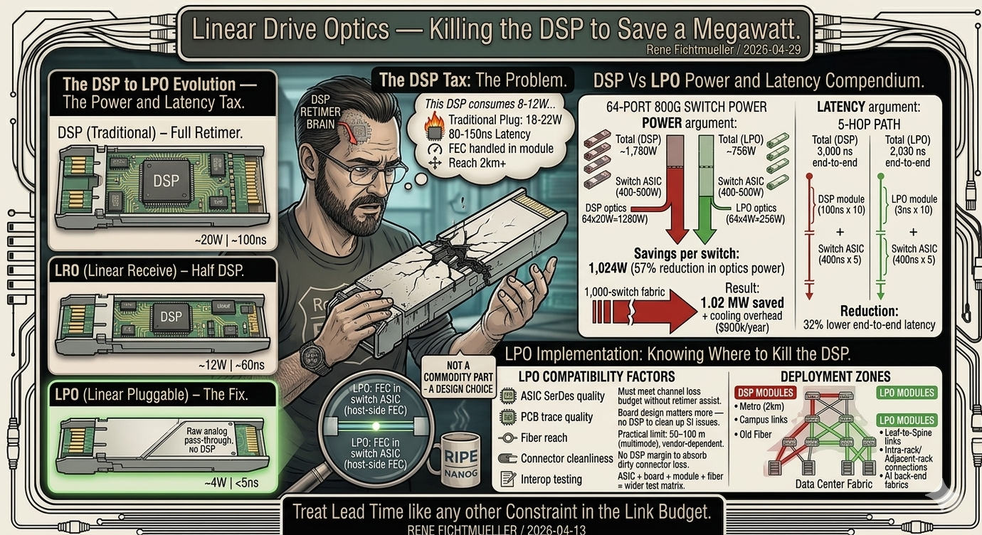
Linear Drive Optics — Killing the DSP to Save a Megawatt
Most modern high-speed DSP-based pluggable optical modules contain a DSP that re-clocks and reshapes the electrical signal. That DSP can consume a significant part of the module power budget. For short-reach links inside a data center, much of that processing may be unnecessary when the host platform and channel are good enough.
LRO (Linear Receive) DSP on transmit, linear (no retimer) on receive
LPO (Linear Pluggable) No DSP/retimer in module. Linear analog path with host-managed signal conditioning.
Module power (800G) DSP: 18–22W | LRO: 10–14W | LPO: 3–6W
Latency (module) DSP: 80–150 ns | LRO: 40–80 ns | LPO: < 5 ns
Reach DSP: long-reach capable | LRO: platform-dependent mid-reach | LPO: short-reach by default, with reach depending on module type and host validation
FEC handling DSP: module/host split depends on implementation | LPO: host-side FEC and equalization are critical
LPO removes the DSP from the module entirely. The optical engine converts electrical signals to light and back. Retiming is removed from the module, and the host ASIC becomes responsible for the electrical channel work that the module DSP used to hide. Equalization, link training and FEC behavior become part of the host/module validation story.
On a clean short-reach link, you stop paying the power and latency tax for retiming that may not add meaningful value.
A spine switch with 64 ports of 800G pluggable optics. With DSP-based modules at 20W each, the optics alone consume 1,280W. With LPO at 4W each, optics consume 256W. The switch-plus-optics power profile changes dramatically.
DSP optics (64×) 64 × 20W = 1,280W
LPO optics (64×) 64 × 4W = 256W
Total (DSP) ~1,780W per switch
Total (LPO) ~756W per switch
Savings per switch 1,024W (57% reduction in optics power)
1,000-switch fabric 1.02 MW saved + cooling overhead
In this example, a 1,000-switch fabric saves just over a megawatt at the optics layer. At $0.10 per kWh, that is roughly $900,000 per year in electricity costs alone, before cooling overhead.
A DSP retimer in the module adds latency. The exact number depends on module architecture, SerDes behavior and measurement point, but the direction is simple: retimed modules add optical-path latency that LPO largely removes. For front-end web traffic, nobody notices. For RDMA-based GPU collective operations, those nanoseconds can matter.
LPO module latency 3 ns × 10 modules = 30 ns
Switch ASIC latency ~400 ns × 5 hops = 2,000 ns (same for both)
Total (DSP) 3,000 ns end-to-end
Total (LPO) 2,030 ns end-to-end
Example reduction Illustrative 32% lower end-to-end latency in this model
The exact percentage will vary by platform, optics type and topology, but the principle holds: removing the module retimer can materially reduce optics-induced latency on the same fabric, switches and fiber.
LPO requires the switch ASIC to drive the optical channel directly. The ASIC SerDes must be clean enough that the signal reaches the far end without mid-path retiming. On very short, clean channels, that is manageable. On a longer fiber path with several patch points, the signal budget gets tight.
PCB trace quality Board design matters more — no DSP to clean up SI issues
Fiber reach Short-reach by default; practical reach is module, fiber and host dependent
Connector cleanliness No DSP margin to absorb dirty connector loss
Interop testing ASIC + board + module + fiber = wider test matrix
Standards base LPO MSA specifications plus OIF CEI-112G-LINEAR-PAM4 / EEI work
Without a DSP to clean up signal integrity problems, the entire channel from ASIC to far-end ASIC must meet tighter specifications. Board layout, trace impedance matching, via design, and connector quality all become more critical. The DSP was masking problems. Removing it exposes them.
LPO fits short-reach, controlled environments where the fiber plant is clean and the switch platform has validated SerDes performance. Intra-rack, adjacent-rack and many AI back-end fabric links are the natural starting point. Some LPO variants target longer single-mode reaches, but the deployment rule stays the same: validate the complete channel, not just the module.
DCI links at 80 km need a DSP. Metro connections at 2 km need a DSP. Campus links through old multimode fiber with questionable connectors need a DSP. LPO is not a replacement for DSP-based optics. It is an alternative for the links where DSP adds cost without adding value.
Your fabric likely has both. Short-reach leaf-to-spine links run LPO. Spine-to-DCI and inter-building links run DSP modules. Two optics strategies for two different jobs. The savings come from knowing which links need what.
This is also why LPO is not just a lab topic anymore. For the right links, it is a practical sourcing decision.
At FLEXOPTIX, we already support Linear Pluggable Optics for exactly these short-reach, high-density environments where power, latency and thermal budget matter. Not every link should be LPO. But the links that can use it should be looked at seriously, especially in AI fabrics and modern leaf-spine designs.
The important part is validation. LPO only makes sense when the host platform, SerDes quality, module, fiber path and operational environment fit together. It is not magic. It is a sharper tool for the right job.
FLEXOPTIX LPO transceivers:
https://www.flexoptix.net/en/transceiver?fo_tra_type=LPO