Your OTDR Is Lying to You
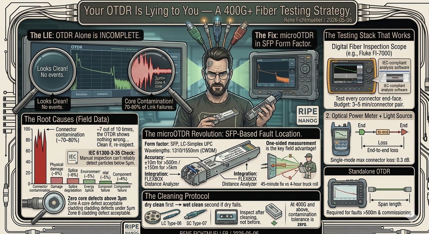
An OTDR finds breaks, splices, and macrobends. It tells you nothing about the cause of 80% of optical link failures: contaminated connectors. Here's what actual fiber testing looks like — and how an SFP-based microOTDR changes the economics.
When a link fails, everyone reaches for the OTDR. An OTDR measures reflection events and attenuation along a fiber — it finds breaks, bad splices, macrobend loss, and connector reflectance. What it does not find is contamination. And contamination causes most failures.
Those numbers come from IEC TR 62627-10 and Corning field service data. The practical version: if a link degrades and your OTDR shows nothing wrong, the connector is dirty. Clean it, re-inspect. In 7 out of 10 cases, the link recovers.
IEC 61300-3-35 defines pass/fail criteria for fiber end-face contamination. Zone A (core): zero defects above 3μm for single-mode. Zone B (cladding): defects under 5μm acceptable. The standard requires a digital inspection scope with IEC-compliant analysis software — not a manual eyepiece. Manual inspection can't reliably detect particles below 5μm. At 400G coherent, 3μm contamination causes 0.3–0.8 dB insertion loss increase. That's the difference between a healthy ZR link and a link that's 6 dB below budget.
An OTDR alone is incomplete for any high-speed link. Three instruments cover the full picture:
1. Digital Fiber Inspection Scope — VIAVI FiberChek Probe, EXFO FIP-400B, Fluke FI-7000. Required for IEC 61300-3-35 pass/fail. Test every connector end-face before mating. Budget 3–5 minutes per connector pair.
2. Optical Power Meter + Light Source — end-to-end insertion loss. Budget loss per connector: 0.3 dB max single-mode. Total span loss must match your link budget ±0.5 dB. If it doesn't, find the problem before the module goes in.
3. OTDR — characterize splices, measure span length, locate macrobend events. Required for runs over 500 meters, and for fault location after any physical incident.
A lab-grade OTDR costs $5,000–15,000 and lives in a case in the office. Most fiber faults happen somewhere else — in a remote IDF, a leased colo rack, or a field cabinet 30km out. Getting the OTDR there takes time and planning.
The Flexoptix S-OB1612-40-XDL changes that calculation. It's a microOTDR in SFP form factor — plugs directly into a FLEXBOX or any compatible SFP cage, runs up to 40km on 21 dB power budget, and connects to the FLEXBOX Distance Analyzer for graphical segment visualization. Accuracy: ±10 meters for spans over 500m, ±150 meters for spans over 5km. Price: €440.
The one-sided measurement is the key field advantage: you don't need access to the far end of the fiber. Plug in at the near end, trigger a measurement, see every reflection event and segment length on the Distance Analyzer graph. For fault location during maintenance, that's the difference between a 45-minute fix and a 4-hour truck roll waiting for the remote site to let you in.
It doesn't replace a full OTDR for commissioning a new fiber plant — the ±150m accuracy at distance and 21 dB power budget fall short of what a standalone unit delivers. But for ongoing maintenance, fault location, and span characterization on links up to 40km, the microOTDR SFP covers 80% of real-world use cases at 5% of the price.
Two-step, non-negotiable: dry clean first, wet clean second if dry fails. Use fiber reel sticks (Cletop Type-06 for LC, Type-07 for SC/MPO) or lint-free cassette cleaners. Never blow with compressed air — it introduces particulates and redistributes existing contamination. Inspect after cleaning, not before. Inspect-then-clean gives you a contaminated scope tip. Clean-then-inspect gives you an accurate baseline.
At 400G and above, contamination tolerance is zero. A dirty connector that caused 0.2 dB loss at 10G causes link failure at 400G ZR. The inspection scope and the cleaning kit pay for themselves on the first prevented outage.